NEMA 4, 4X, and IP66/67 Certified Switch Box for Harsh Environments
Reliable Monitoring for Quarter-Turn Actuators in Harsh Environments
More Details
Features & Benefits
-
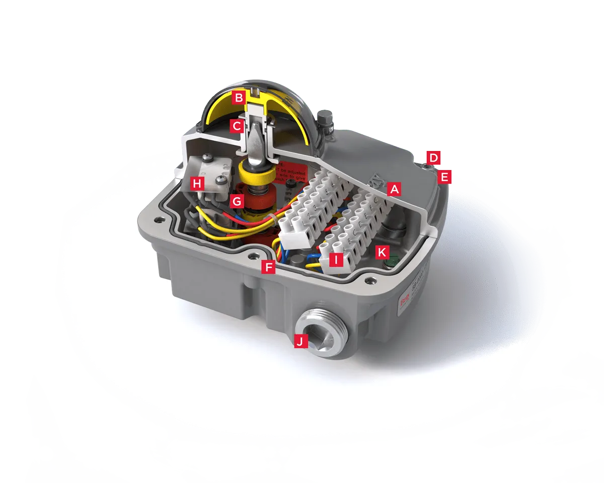
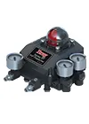
A. Enclosure
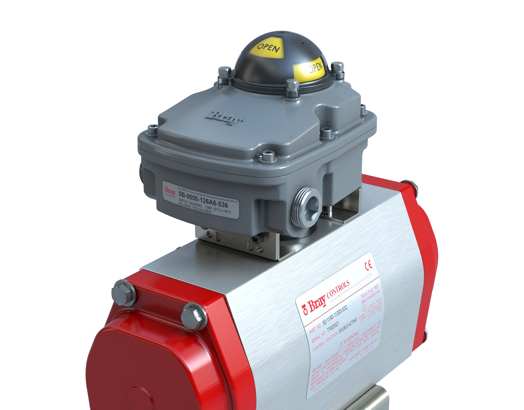
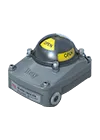
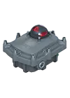
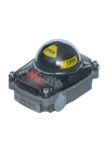
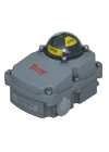
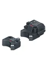
The compact low profile weatherproof VSM is UL certified NEMA Type 4, 4x and IP66/67. Aluminum base and cover for exceptional corrosion, wear and impact resistance.
-
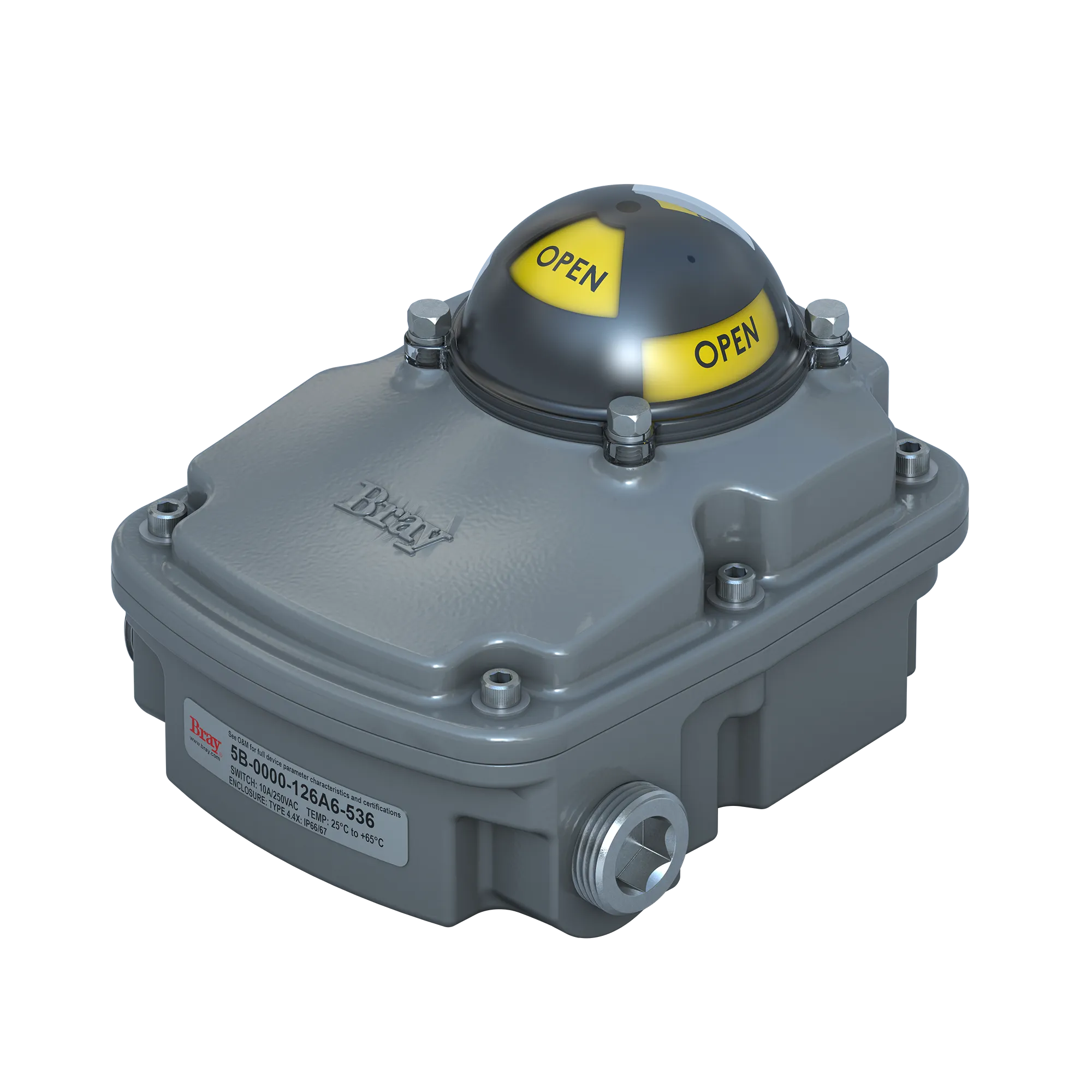
B. High Visibility Position Indicator
Visual open and closed indication is provided with an impact resistant dome style indicator. Inverting the open and closed visual output is easily done by rotating the indicator dome 90 degrees. There is no need to remove the switchbox aluminum cover and expose internal wiring of the VSM to change position indication.
-
C. Stub Shaft Secondary Seal
Ensures indicator area is separate from the VSM’s internals. Provides a secondary seal to prevent water ingress should the dome or dome seal become compromised due to adverse site conditions.
-
D. Captive Cover Bolts
The cover is attached to the base by captive stainless steel bolts placed outside the sealing area.
-
E. Protective Washers
Clear, nonmetallic, corrosion resistant washers are used to ensure coating integrity when cover bolts are tightened.
-
F. O-Ring Seal for Watertight Enclosure
The O-ring seal between the cover and base provides a weatherproof seal to prevent water ingress and internal corrosion.
-
G. Sensor Cams
Splined cam design allows for easy and accurate setting of switch activation without the use of tools.
-
H. Limit Switches
Up to six switch options and configurations to meet connectivity requirements.
-
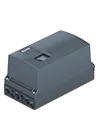
I. Terminals
Clearly marked terminal blocks are angled towards the user to ensure easy access.
-
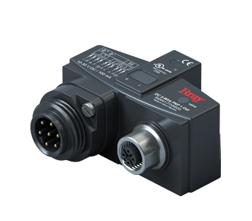
J. Conduit Entries
Two conduit entries available in either imperial or metric threads.
-
K. Grounding
Green color-coded, easy-access grounding bolt.
Explore More Bray Insights
Learn Even More About How Bray’s Solutions Can Impact Your Business
Valve Solutions for Refining, Production & Distribution
Oil & Gas
Bray provides a comprehensive line of valves, actuators, and accessories for oil & gas production, distribution, and refining. Trusted in demanding applications like oil sands, natural gas, and severe service.
Explore Our Oil & Gas Solutions
Reliable Valve Solutions for the Chemical Industry
Chemical & Petrochemical
Bray, a global leader in high-performance valves, ensures safety, reliability, and efficiency for chemical applications, from basic chemicals to specialty polymers, supporting industry growth and innovation.
Discover More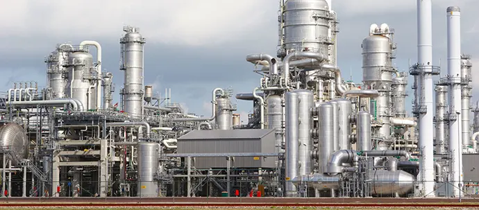
Proven Reliability in Water and Sewage Treatment
Water & Wastewater
Bray offers a comprehensive line of valves, actuators, and controls for municipal water supply, treatment, distribution, sewage, desalination, and ultrapure water purification, ensuring reliable service.
Learn More About Our Products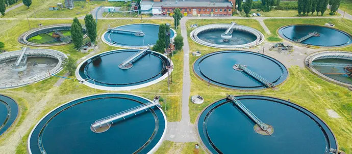
Reliable Multi-Port and Custom Valves for Pharmaceutical Manufacturing Processes
Pharmaceuticals & Biotechnology
Bray provides innovative Valve Solutions to Pharmaceutical and Biotech Companies, enhancing efficiency and agility while reducing costs in a competitive landscape.
Bray Pharma & Biotech Solutions
Contact Us
Request a Quote